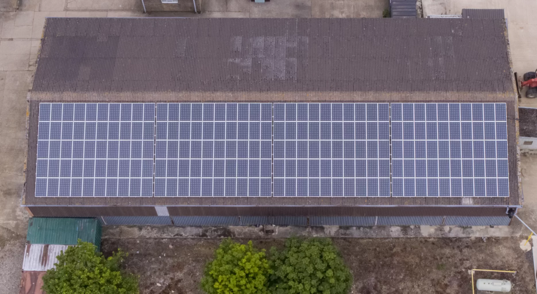
The Roof Comes First, the Array Fits Around It
Almost no domestic solar array is laid out the way anyone would draw it on a blank sheet. The roof arrives first, and the array is fitted into what the roof leaves over. Pitch is whatever the builder set, orientation is whichever way the house was turned when the street was laid out, and the usable area is whatever remains once the chimney, the vent stacks, the dormer and the shadow of next door’s conifer have taken their share.
The result is a layout that looks arbitrary from the pavement and is nothing of the kind. Every row sits where it does for a reason, and those reasons were settled on installation day by people working around fixed obstacles.
What is less obvious is that the same decisions quietly settle something else. They fix the plane the modules sit in, and therefore the directions from which those modules can usefully be looked at afterwards. A thermal inspection is a geometry problem before it is anything else, and the geometry was decided years earlier by a roof.
This piece is about that link. It covers how a domestic array ends up in the shape it is in, why that shape makes a rooftop array awkward to assess from ground level, and what a homeowner can usefully keep on file so the array can be surveyed properly when the time comes.
Blog Content TL;DR...
The short version, for anyone with panels already on the roof.
- A domestic array is not designed on a blank sheet. Pitch and orientation are inherited from the building, and shading from chimneys, dormers and trees removes usable area before the layout is drawn.
- What gets installed is the residual, which is why domestic arrays are so often irregular, interrupted, or split across two faces of the same roof.
- Those same decisions fix the plane the modules sit in, and so fix the directions from which they can be usefully imaged later.
- Seen from ground level, a pitched roof presents its panels at a very shallow angle, where the cover glass increasingly reflects the sky and the surroundings instead of showing its own thermal signature.
- An array split across two roof faces has no single viewing position that serves both, so survey positions have to be planned around the layout the installer was forced into.
The decisions taken on installation day determine what can be seen afterwards, which is why the roof, not the panel, is the thing that shapes the survey.
The Roof Gets the Final Say
Pitch, orientation and obstruction decide the layout long before anyone counts panels
Pitch and Orientation Are Inherited, Not Chosen
A ground-mounted array can be set at whatever angle and bearing suits the site. A domestic roof offers no such freedom. The pitch was fixed when the roof was framed, and it was chosen for shedding rain and carrying tiles rather than for collecting light. The orientation is fixed even more firmly, because it depends on how the house was placed on its plot, which in turn depends on how the street was laid out long before anyone thought about solar.
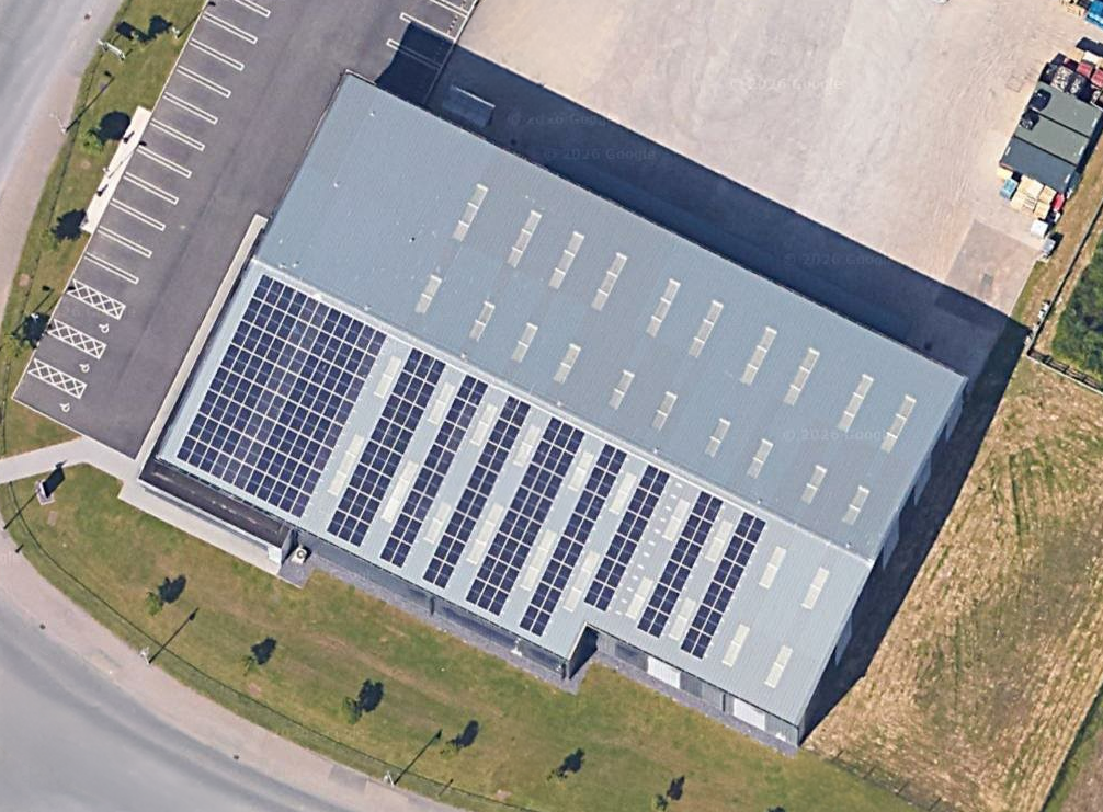
An installer therefore starts with the module plane already determined in both axes. Where a house presents more than one suitable pitch, the array is often split across two of them, which is a sensible answer to a shortage of area on any single face. It also means the finished installation has two module planes rather than one, facing in different directions.
Shade Removes Area Before the Design Starts
Shading is the constraint that does most damage to a tidy layout, and it is rarely uniform. A chimney throws a moving shadow across part of the roof for part of the day. A dormer, a satellite dish, a soil vent pipe or a neighbouring gable does the same on a smaller scale. Trees are the awkward case, because their shadow changes through the year and grows over the life of the installation.
What Gets Built Is the Residual
By the time all of that has been allowed for, the shape available for panels is whatever is left. Rows get shortened to clear an obstruction, a column is dropped where a vent sits, and the array ends up as an irregular block, or two, packed into the clear ground. That is good practice rather than bad. It is simply worth recognising that the layout is a residual, and that nothing about it was arranged for the convenience of anyone looking at it later.
why roof pitch decides a domestic solar panel layout, inspecting solar panels on a pitched house roof, roof shading and domestic solar array designwhy roof pitch decides a domestic solar panel layout, inspecting solar panels on a pitched house roof, roof shading and domestic solar array design
Geometry Fixed on Installation Day
A thermal image of a module is a measurement of the radiation leaving its surface, and that measurement depends on where the camera is standing. Look at the module face on, and almost everything reaching the lens has come from the module. Look at it from a shallow angle, and an increasing share of what reaches the lens is the sky, the surroundings and, at the worst of it, the person holding the camera, reflected off the cover glass. The module has not changed. The view of it has.
Why a Shallow View Stops Working
IEC 62446-3:2017, the technical specification covering outdoor infrared thermography of photovoltaic systems, deals with this directly. It asks for the image to be taken as close to perpendicular to the module surface as possible, and gives a minimum angle of view of 30 degrees, measured from the module surface itself, specifically to limit the effect of reflected background. It also states that reflections of the survey personnel and their equipment are to be avoided.
Now stand on the lawn of a house with a pitched roof and picture the line from a camera to a panel near the ridge. It is a long, shallow, upward line that meets the module plane at a small angle, and it is looking at glass tilted away from you and towards the open sky. That is close to the least favourable geometry the standard contemplates, and no amount of care with the camera converts it into a good one. The array is not awkward because it is high up. It is awkward because of the direction it is pointing.
What This Means When the Array Is Surveyed
One Position Will Not Serve Two Planes
If an array is split across two faces of a roof, no single vantage point is square to both. Each plane has to be approached on its own terms, which is a planning matter rather than a difficulty. The same standard that gives the minimum angle also sets a minimum recorded resolution across every cell, and requires that resolution to be achieved even at the least favourable angle, so simply backing further away to improve the angle eventually costs the detail. Angle and distance have to be solved together, and the roof decided both.
Keep What the Installer Handed Over
The most useful thing a homeowner can do is keep the installation paperwork. A layout drawing showing which panels sit on which plane, and how they are grouped, turns a survey from an exercise in guesswork into a straightforward comparison against the design. Where a survey does identify something, it is reported as an area warranting further investigation by a suitably qualified contractor, never as a repair instruction. Drone Media Imaging provides the survey, the analysis and the reporting, and the roof itself is the reason that work is planned around the array rather than around the house.

IEC TS 62446-3:2017 covers outdoor infrared thermography of photovoltaic modules and plants in operation. Two of its provisions bear directly on roof geometry.
On angle, the imaging procedure requires the image to be taken as perpendicular to the module surface as possible, and requires that self-reflection of personnel and apparatus, and reflection of heated objects such as the sun, nearby buildings and trees, be avoided. Where a perpendicular image is not achievable, the normative annex gives a minimum angle of view of 30 degrees, measured from the module surface rather than from its normal, to minimise the effect of reflected background.
The reason sits in the optics of the cover glass. The specification notes that the emissivity of non-ferrous glass falls as the angle of view becomes shallower, to around 0.8 at 45 degrees and around 0.75 or lower at 30 degrees.
On resolution, the same annex requires all modules, including those observed at the least favourable 30 degree angle, to be recorded at a minimum of five by five pixels per cell.
Governing Standards and Competence
- IEC TS 62446-3:2017, Photovoltaic (PV) systems, requirements for testing, documentation and maintenance, Part 3: Photovoltaic modules and plants, outdoor infrared thermography. Methodology aligned as applicable.
- Thermographic analysis conducted by Steve Fisher, ITC Level III Certified Master Thermographer (Infrared Training Centre; Certification #205722059), practising in accordance with the frameworks of ISO 18436-7:2014, ASNT SNT-TC-1A and ANSI/ASNT CP-105, and BINDT CMGEN Appendix B as UK training governance.
- Flight operations are conducted under a Civil Aviation Authority Operational Authorisation, with a General VLOS Certificate and an A2 Certificate of Competency.
- Electrical scope, where it is included, is string-level testing only. No inverter diagnostics, switchboard wiring or on-roof electrical work is undertaken.
- Drone Media Imaging provides survey, analysis and reporting services. No chartered surveying designation is held or implied, and no structural or roofing opinion is offered on the condition of a roof covering.
Solar Surveys Planned Around Your Roof
Every roof presents its array differently, so the survey is planned around the layout rather than the other way round. Tell us the address, roughly how many panels are up there and whether they sit on one roof face or more, and you will get a straightforward quotation for the survey, the analysis and the report.
Drone Media Imaging covers Sussex, Hampshire, Kent and Surrey, travelling throughout the UK, Ireland and Europe, with thermography undertaken worldwide.
related posts

Every drone flight starts and ends on somebody's ground, and an aviation authorisation gives no right to it. This post explains the two separate permissions a professional flight needs, the air and the ground, what happens when the client controls a site but does not own it, why the best vantage point is often next door, why public land and roads are rarely the answer, and how Drone Media Imaging settles the take-off point during planning rather than on the day.