Standoff Distance in Aerial Inspection
The instinct on an inspection is to get closer. Something looks wrong on a roof, a facade or an array, so the aircraft moves in until the detail fills the frame. It feels like diligence, and on most sites it is the least useful thing the pilot can do.
Standoff is the deliberate decision to hold the camera back from the asset and let the optics do the closing. It separates the aircraft from the structure it is inspecting, and it separates the operation from the people working below. On a live industrial site, a running plant or a structure of uncertain condition, that separation is the whole point of using an aerial platform at all.
But standoff is not a free good, and it is not simply a matter of flying further away and zooming in. The distance is a calculated figure, governed by how much of the target each pixel has to cover and by the angle the camera holds to the surface. Get either wrong and the imagery looks impressive and answers nothing. Distance is a data-quality decision before it is a safety one. What follows sets out what standoff buys on a working site, what actually governs the number, and where the limits sit.
Blog Content TL;DR...
Why aerial inspection works better from further back, and what decides how far.
- Standoff holds the camera clear of the asset and lets the optics close the gap, keeping the platform out of the hazard volume and the operation away from people below.
- Getting close does not just add risk, it changes the thing being measured, through rotor wash, self-reflection and the platform’s own shadow.
- The working distance is calculated, not judged. It follows from the resolution required on the target surface and the sensor’s instantaneous field of view.
- Angle matters as much as range. Beyond roughly 60 degrees from the surface normal a thermal frame is not valid for measurement, however sharp it looks.
- A radiometric thermal measurement takes distance itself as an input, so it can never be treated as a zoomed optical view.
Standoff is chosen against a figure, not maximised for comfort.
Why Distance Is the Point
Closing in on an asset costs more than it returns, and some of the cost lands in the data
Proximity Is a Cost, Not a Method
Approaching an asset closely puts the platform where the hazards are. Rooftop plant, cabling, guy wires, chimneys, working machinery and moving people all sit in the volume an aircraft would have to occupy to fill the frame from a short range. Closing that gap also removes the margin available if something goes wrong, and it puts the operation directly above or beside whoever is working on site. Every metre gained in apparent detail is bought from the safety case.
There is a second cost, and it is the one that surprises people. Getting close changes the thing being measured. Rotor wash close to a surface cools it, the platform’s own reflection can appear in glass and polished cladding, and the aircraft’s shadow crosses the very area under examination. On a thermal survey those three effects do not merely spoil the picture, they corrupt the data the survey exists to collect.
What Standoff Actually Buys
Holding the camera back and reaching in optically inverts the trade. The platform stays outside the hazard volume, the people below stay outside the operating area, and the surface being inspected is left undisturbed. The inspection can also continue in circumstances that would stop a close approach altogether, a structure of unknown condition, a live process that cannot be shut down, or an area where nobody should be standing.
None of that is an argument for standing as far back as the optics will allow. It is an argument for choosing the distance deliberately, against a figure, rather than flying to whatever range feels comfortable on the day. That figure is set by the survey rather than by the camera, and it is arithmetic rather than judgement.
How far should a drone stand off an asset, Resolution on target in aerial inspection, Viewing angle limits for a thermal surveyHow far should a drone stand off an asset, Resolution on target in aerial inspection, Viewing angle limits for a thermal survey
What Sets the Number
Resolution on Target
The governing figure is how much of the real surface each pixel has to cover, expressed as centimetres per pixel on the plane inspected. It follows from the sensor’s instantaneous field of view and the distance to the surface, so fixing the required detail fixes the maximum working distance. Drone Media Imaging works its solar photovoltaic capture to three centimetres per pixel on the module plane, fine enough to resolve an individual cell across roughly five pixels, and roof thermal surveys are flown to the same figure.
Two consequences follow. The distance is measured to the surface being inspected, not to the ground, so on a roof it is the height of the roof plane plus the standoff above it. A coarser figure is not a softer target to be traded away on the day; past it, the defect the survey was commissioned to find is not resolvable in the data.
Angle Matters as Much as Range
Standing back is only half the geometry. The angle the optical axis holds to the surface governs both measurement validity and what the surface reflects into the lens. Drone Media Imaging’s solar protocol targets an optical axis within 25° of the surface normal, treats up to 40° as acceptable, and rules frames beyond 60° invalid for measurement. A long lens used from an oblique position will produce a sharp image of a surface it cannot correctly measure.
Range and angle also pull against each other in practice. Holding a tight angle to every plane of a pitched roof or a tilted array means repositioning rather than panning, and standoff makes each reposition a longer move. That is a planning cost, and a better one to carry than a dataset of frames captured out of tolerance.
Where Standoff Stops Paying
The Point of Diminishing Return
Optical reach is not unlimited, and the limit arrives before the image looks bad. Magnification amplifies every small movement in the platform and the mount, so the further back the camera sits the more the stability of the whole system, rather than the lens, decides whether the frame is usable. Atmospheric haze, heat shimmer off a warm surface and low sun all degrade a long shot in ways that are easy to miss on a small screen in the field.
The practical answer is that standoff is chosen, not maximised. The distance is set at the figure the required resolution allows, with the angle held inside tolerance, and the platform is then held there. Anything further back is a choice to collect less information than the survey was commissioned to produce.
A Thermal Measurement Is Not a Zoomed View
The most important limit is the one least often stated. A radiometric thermal survey does not simply photograph heat, it calculates a temperature from what the sensor receives, and that calculation takes emissivity, reflected apparent temperature, ambient temperature, relative humidity and the distance itself as inputs. Distance is a parameter in the measurement, not just a framing decision, so changing it without recording it changes the answer. That is why a thermal capture plan records the standoff and the environmental readings for every session.
Findings from either route are reported as areas warranting further investigation by a suitably qualified contractor, which is the honest limit of any inspection conducted from a distance. Survey, analysis and reporting is what the standoff makes possible. Deciding what to do about what it shows belongs to somebody standing on the structure.

Standoff is calculated before the flight, not judged during it. The required detail on the target plane is fixed first, as centimetres per pixel; Drone Media Imaging works solar photovoltaic and roof thermal capture to three centimetres per pixel on the surface being inspected. The maximum working distance then follows from that figure and the sensor’s instantaneous field of view, and it is measured to the surface itself rather than to ground level, so for a roof it is the height of the roof plane plus the standoff above it.
The angle is planned alongside it. The optical axis is held as near perpendicular to the surface as the reflection allows, with a small deliberate offset so the platform does not appear in its own frame, and the sun kept off the mirror axis. On a radiometric capture, the distance that results is entered into the camera along with emissivity, reflected apparent temperature, ambient temperature and relative humidity, and logged for each session.
Discuss an Aerial Inspection
If an asset is difficult to approach, or approaching it would disturb what you need measured, tell us what you need to see and we will work back to the capture distance and geometry that will show it. Drone Media Imaging covers Sussex, Hampshire, Kent and Surrey, travels throughout the UK, Ireland and Europe, and undertakes thermography work globally.
related posts
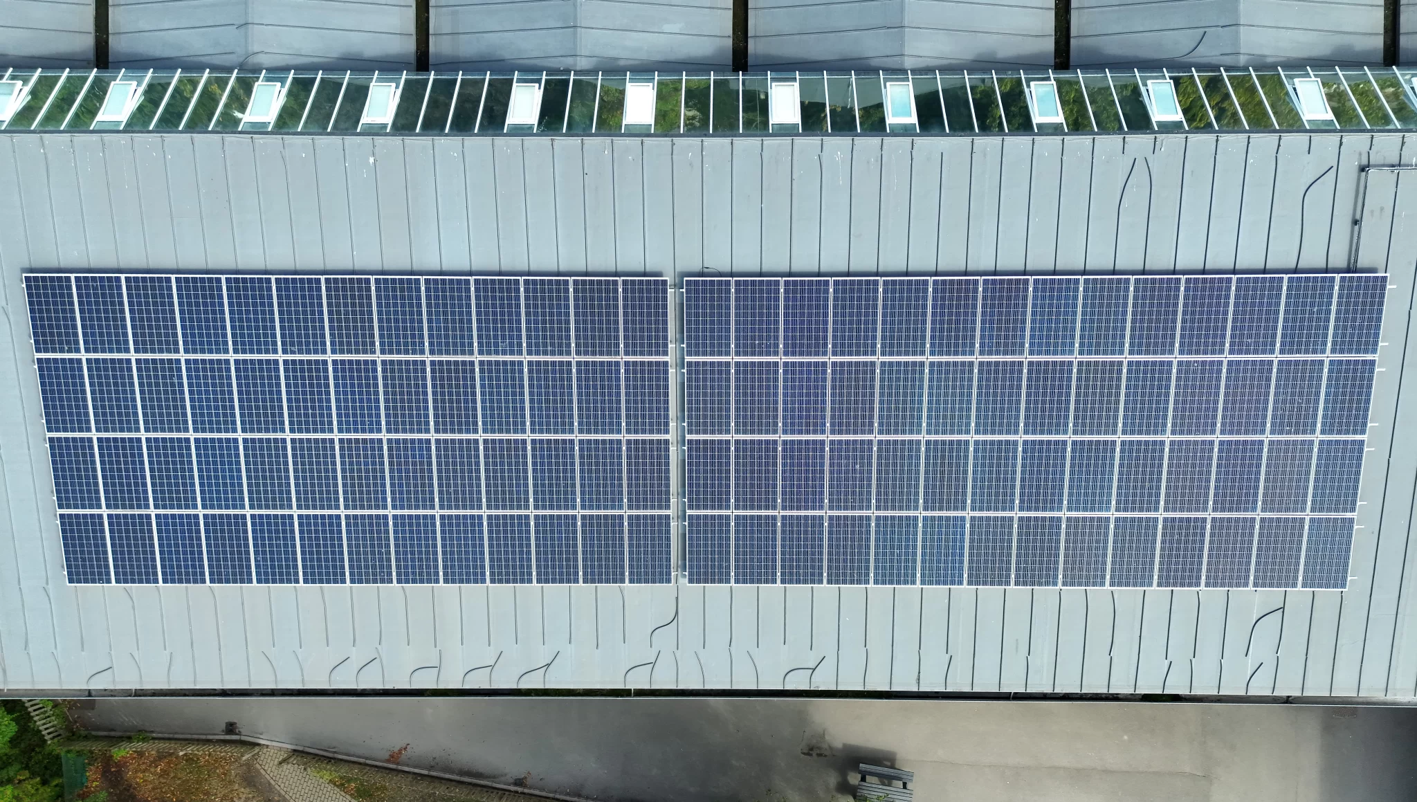
A commercial rooftop solar array sits on somebody's working building, and that single fact decides how it gets inspected. Getting a person to roof level means access equipment and a permit, and the roof covering is not always capable of carrying them. It also puts the camera in the wrong place: IEC 62446-3 wants the thermal image taken square to the module, which nobody standing on a pitched roof can manage. Here is why the survey is flown instead.

How close can a drone legally fly to people and buildings in the UK? This piece sets out the ground rules in plain terms: the Open category subcategories A1, A2 and A3, the 120 m height limit, the separation kept from uninvolved people and from residential, commercial, industrial and recreational areas, what "uninvolved" means for your own staff and visitors, and why a Specific category Operational Authorisation is what lets a commercial operator work closer on a busy site.
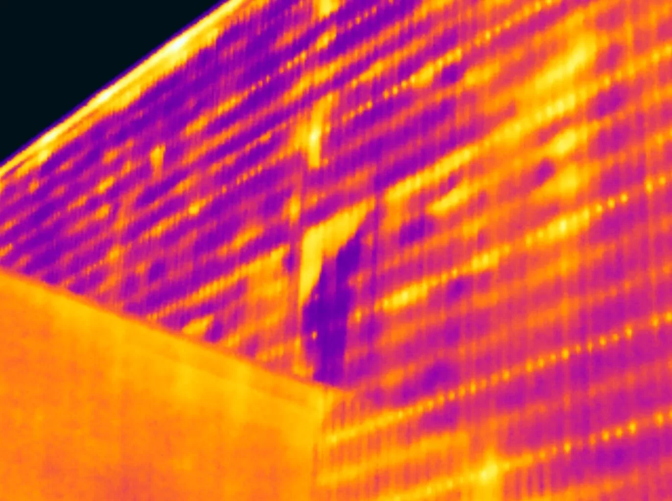
Thermography, a non-invasive technique that uses infrared imaging to detect temperature variations, has emerged as a powerful tool in the field of building diagnostics. By capturing thermal images of structures, thermography enables professionals to identify areas of heat loss and energy inefficiency. This article explores the benefits of using thermography to pinpoint heat loss in structures, providing valuable insights into how this technology can help improve energy efficiency and reduce carbon emissions.