How Solar Panels Are Wired: Cells, Modules, Strings and Arrays Explained
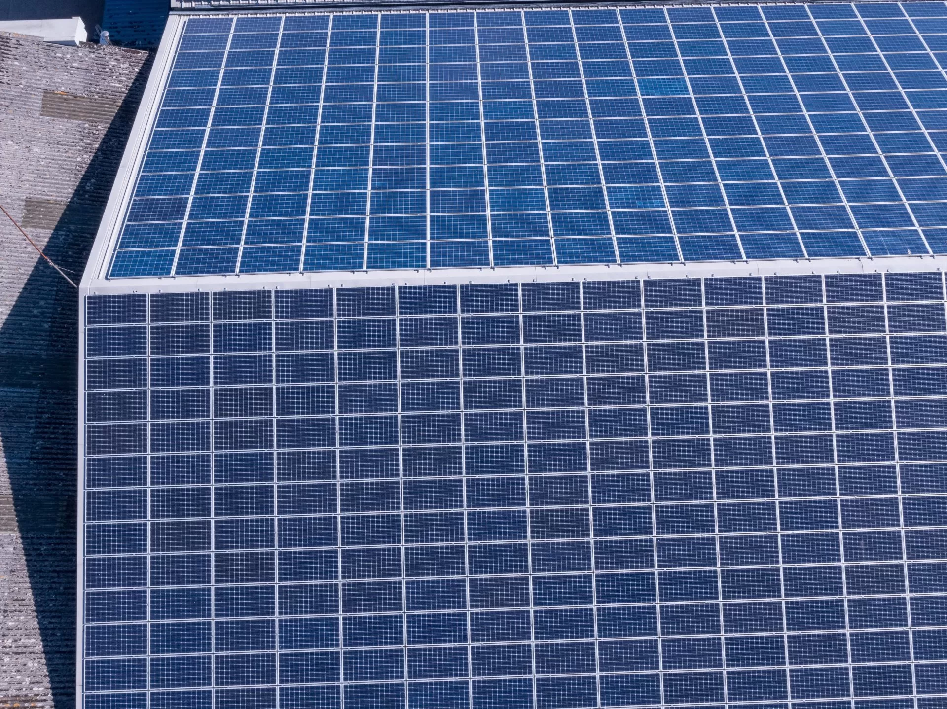
A solar installation looks like a grid of identical rectangles on a roof. Electrically it is nothing of the kind. It is a hierarchy, four levels deep, and each level is wired to the ones above and below it in a way that is invisible from the air.
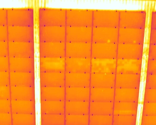
A thermal camera does not see that hierarchy. It sees surface temperature across a plane. The interpretation, the part that turns an image into a finding, is entirely a matter of working out which level of the structure a warm area belongs to. A mark that stops at one cell edge and a warm block covering many modules at once come from completely different mechanisms, and they are addressed by completely different people.
So the question that actually has to be answered on any solar thermogram is one of attribution. What is this warm area a picture of? One cell, a group of cells sharing a protective diode, a whole module, or a whole series chain running back to an inverter input. Until that is settled, nothing else on the report can be.
This piece works up through that structure, from the individual cell to the array, and sets out why the wiring diagram is as much a survey document as the imagery is.
Blog Content TL;DR...
A thermal survey of a solar array is an exercise in attribution, and the wiring decides what you are looking at.
- A photovoltaic installation is a four-level hierarchy, cell to module to string to array. Each level fails differently and is addressed by a different trade.
- Cells are wired in series, so every cell in a chain carries the same current and the weakest element sets the output for all of them.
- Bypass diodes divide a module into sub-strings, and the number of those groups, rather than the fault, decides what fraction of the module behaves as a unit.
- Module construction changes the arithmetic. A half-cut module is partitioned differently from a full-cell module, so the same event covers a different area.
- Without the as-built string layout, a survey can describe where a warm block sits but cannot name the circuit it belongs to.
The camera records the roof. The fault lives in the circuit, and only the wiring connects the two.
Four Levels, Not One Surface
What is actually underneath the flat grid a survey photographs

The cell is the only thing that generates
Everything in a photovoltaic installation is built upward from the cell. A single silicon cell converts light directly into electrical current, and it does so at a fraction of a volt. That is useful for nothing on its own, so cells are connected in series, positive to negative, and the voltages add up until the chain reaches something a piece of equipment can work with. A module, the object most people call a panel, is that series chain laminated behind glass with a frame around it.
The series connection is the single most important fact in the whole structure, and it is the reason a thermal survey works at all. In a series circuit every element carries the same current. A cell cannot produce more current than its neighbours are willing to pass, which means the weakest cell in the chain sets the current for all of them. When a cell is shaded, cracked or internally damaged, it does not simply contribute less. It becomes a restriction that the rest of the chain is pushing current through, and the energy the healthy cells are still producing has to go somewhere. It goes into heat, at the point of the restriction.
That is why a fault in a solar array announces itself thermally rather than visually. The damaged element is being driven by the healthy ones around it, and the heat is the by-product of that argument between them.
how are solar panels wired together, what is a string in a solar PV system, why do solar modules have bypass diodeshow are solar panels wired together, what is a string in a solar PV system, why do solar modules have bypass diodes
The Module Is Not One Block
Why a module is divided into sub-strings
If a module were a single unbroken series chain, one shaded cell would throttle the output of every cell behind it, and a leaf landing in the wrong place would cost the whole panel. Manufacturers solve that with bypass diodes. A diode is fitted across a group of cells, and when the voltage across that group reverses, which is what happens when the group stops producing and starts resisting, the diode conducts and carries the current around it instead of through it. The group carries on doing nothing useful, but the rest of the module keeps working.
This is the level of the hierarchy most people have never heard of, and it is the one that shapes what a survey actually sees. The diode does not protect a cell, and it does not protect a module. It protects a sub-string, a defined block of cells decided in the factory. When that diode conducts, the whole block it covers changes thermal behaviour together, because the whole block has been taken out of the circuit at once.
The arithmetic is set by the module, not by the fault
How much of a panel that block represents depends entirely on how the module was built. A conventional full-cell module is commonly partitioned into three diode groups. A half-cut module, which splits every cell in two and is now the mainstream construction, is typically partitioned into six. The same underlying event therefore warms a different fraction of the panel on the two designs, and that fraction is a fact about the module rather than a fact about the fault.
Reading the extent of a warm area without knowing the construction is guesswork dressed as measurement, which is why the module type is recorded at survey rather than inferred from the imagery afterwards.
What the Camera Cannot Tell You About the Circuit
The string is a chain you cannot see
Above the module sits the string, a number of modules wired in series and landing on a single input at the inverter. The string is where the structure stops being visible. Two modules sitting side by side on a roof may be on different strings, and two modules at opposite ends of the same roof may be on the same one, because the installer routed the cabling to suit the building, the cable runs and the inverter position rather than to suit anyone looking at it later from above.
The array is a set of parallel chains
Several strings then connect in parallel to make the array, at a combiner box or directly at the inverter. That parallel arrangement is why a condition affecting one string leaves its neighbours untouched, and why a condition upstream of the strings can affect a whole section of the site at once. Where module-level electronics are fitted, the boundaries move again, and what counts as a string on that site is not what it would be on a conventional installation.
Why the wiring diagram is a survey document
All of which leads somewhere practical. A thermal survey can establish, from the imagery alone, that a block of modules is behaving differently from the rest of the site. It cannot establish from the imagery alone that the block is a string, or which string it is, because that information was never on the roof to be photographed. It lives in the as-built documentation, the string layout and the inverter schedule.
Without those, a report names a location. With them, it names a circuit, and a circuit is something an operator can go and test. That is the difference between an observation and a finding worth acting on, and it is why the paperwork is requested before the flight rather than after the analysis. A thermographic survey identifies and evidences a condition at the time of inspection. The findings are areas warranting further investigation by a suitably qualified contractor, and naming the right level of the hierarchy is what makes that investigation short.
Cell. The generating unit. Silicon, producing current directly from light at a fraction of a volt, connected in series with its neighbours so that all of them carry the same current. Damage here is localised to one cell footprint.
Sub-string. A group of cells sharing one bypass diode. The grouping is a manufacturing decision, commonly three groups in a full-cell module and six in a half-cut module, and it sets the fraction of the panel that behaves as a unit.
Module. The laminated assembly of cells, diodes, junction box and frame. The unit the client counts, the unit the report references, and the smallest item that can be physically replaced without touching the wiring of the string it sits in.
String and array. Modules in series to one inverter input, then strings in parallel to form the array. Conditions at this level are electrical rather than modular, and confirming them is string-level testing under IEC 62446-1, not thermography. The survey identifies where to look; the electrical test confirms what is happening.
Governing Standards and Scope
- IEC TS 62446-3:2017, outdoor infrared thermography of photovoltaic modules and plants in operation, the methodology this work is aligned to.
- IEC 62446-1, photovoltaic system documentation, commissioning tests and string-level electrical verification, which is where a suspected string condition is confirmed.
- Surveys conducted by Steve Fisher, ITC Level III Certified Master Thermographer (Infrared Training Centre; Certification #205722059).
- Practising in accordance with the frameworks of ISO 18436-7:2014, ASNT SNT-TC-1A and ANSI/ASNT CP-105, and BINDT CMGEN Appendix B as UK training governance.
- Survey, analysis and reporting only. Drone Media Imaging carries out no remedial or corrective work, and findings are areas warranting further investigation by a suitably qualified contractor.
Book a Solar Thermographic Survey
Drone Media Imaging carries out thermographic surveys of rooftop and ground-mount photovoltaic arrays aligned with IEC TS 62446-3:2017, with the flying, the analysis and the reporting done by the same certified thermographer. Where the as-built string layout and inverter schedule are available, findings are referenced to the circuit rather than only to a position on the roof. Coverage across Sussex, Hampshire, Kent and Surrey, travelling throughout the UK, Ireland and Europe.
related posts
Hiring a drone operator does not make you responsible for the flight, but it does make the choice of operator yours. Since the rules changed at the end of 2020 there is no commercial drone permission as such: the category is set by the risk of the flight, and work on a working site normally needs a Civil Aviation Authority Operational Authorisation held by the operator. This article explains who carries what, and what a competent operator should show you before flying.

A site owner's question is usually whether a drone is allowed. The regulations answer a different one: how far the aircraft must stay from people who are not part of the operation. That distance is not fixed. It moves with the authorisation the operator holds, the mass and class of the aircraft flown, and how the people on site are briefed. This is what actually decides whether a working site can be flown, and the small part the client plays in it.

Drone Media Imaging invests in new cuttin-edge photobrapmmetry survey and inspection equipment with the new DJI M300RTK and P1 Suvery Grade Camera