Solar PV Thermographic Inspection of a School Rooftop Array
IEC 62446-3 Solar Thermal Inspection on a School Roof
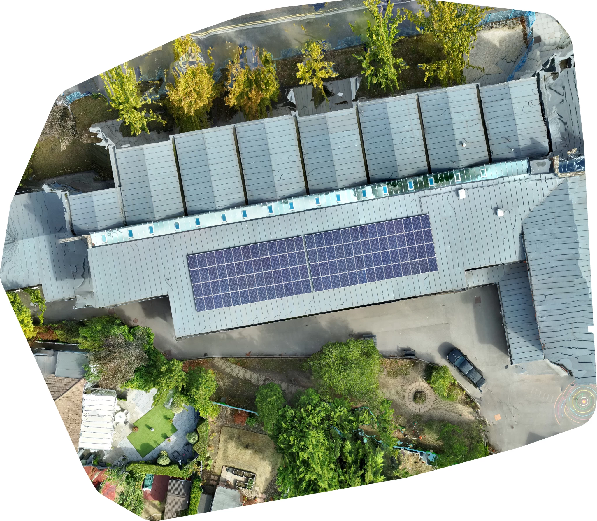
Drone Media Imaging carried out a solar PV thermographic inspection of a rooftop array serving a school site in the South of England, delivered as a detailed inspection under IEC 62446-3:2017. The array comprises 108 modules on a single roof plane, rated at 29.2 kWp and served by one inverter carrying eight strings. Capture was by uncrewed aircraft at 20 m above the module surface while the array was on load and generating, with in-plane irradiance measured at both ends of the survey window and recorded above the 600 W/m² minimum the standard requires. Seven thermograms were analysed, each against a healthy reference module within the same image, so that changing irradiance and ambient temperature across the survey could not distort the comparison. No module carried a classified anomaly. Two sub-threshold observations at cell scale were recorded for monitoring rather than classified as faults. The result is certified against the numerical threshold applied, which is what makes a clear finding checkable rather than merely reassuring.
Project Overview
Subject
solar PV thermographic inspection, rooftop solar array survey, South of England, school and academy estates, IEC 62446-3:2017
Skills Used
IEC 62446-3 Solar Thermographic Inspection, Delta-T Assessment, Level 3 Report Writing
Portfolio Tags
Solar PV Inspection, Rooftop Solar Array, Aerial Thermographic Survey, South of England, IEC 62446-3:2017, Education Estates, Drone Media Imaging, What Does A Clear Thermal Inspection Prove?
Solar Panel Thermal Inspection For Schools, Drone Thermographic Survey Of A Rooftop PV Array, IEC 62446-3 Detailed Thermographic InspectionSolar Panel Thermal Inspection For Schools, Drone Thermographic Survey Of A Rooftop PV Array, IEC 62446-3 Detailed Thermographic Inspection
Solar PV Thermographic Inspection of a School Rooftop Array
~ A clear result is only worth having if it names the test the array passed. ~
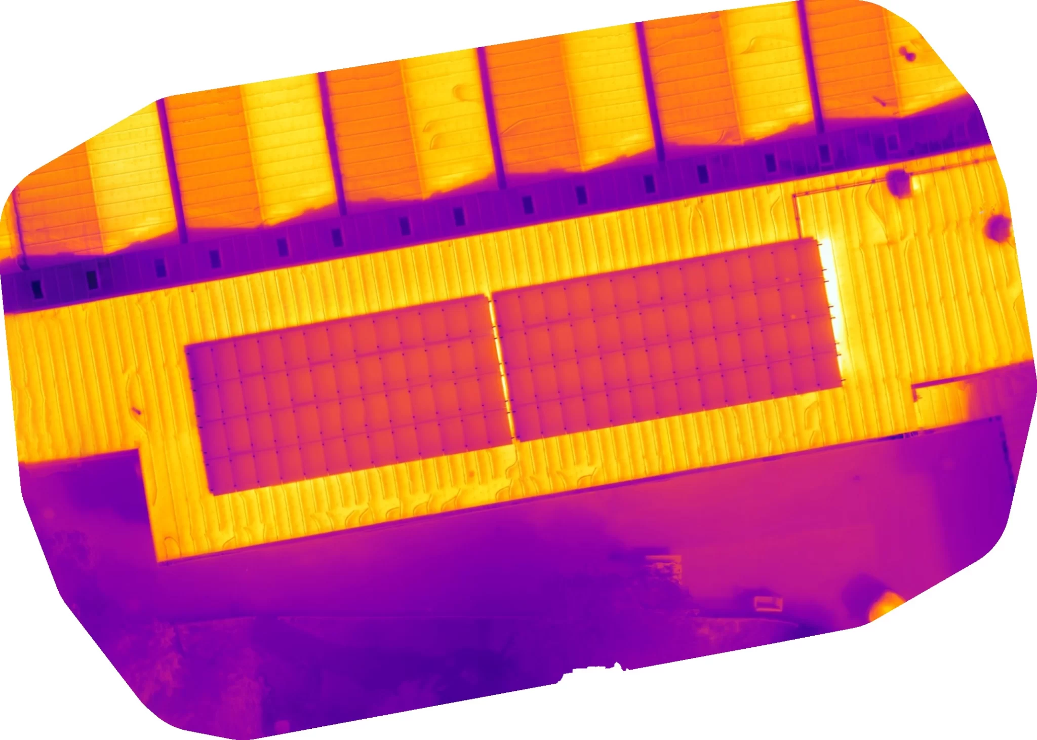
A small array still carries the same failure mechanisms as a large one.
IEC 62446-3 Solar Thermal Inspection on a School Roof
The site is a school in the South of England carrying a rooftop photovoltaic array of 108 modules on a single plane, rated at 29.2 kWp. Arrays of this size sit in an awkward position within an education estate. They are large enough to matter to the energy budget and to the building fabric beneath them, but small enough that they are rarely the thing anyone is looking at. Inspection tends to arrive either after a performance question has already been asked, or as part of a planned programme across a portfolio of sites. This survey was the second kind.
Drone Media Imaging was commissioned to carry out a thermographic inspection of the array under IEC 62446-3:2017. The brief was condition assessment only. Electrical string testing was outside the scope of this engagement and none was carried out by Drone Media Imaging. That distinction matters, because the two methods answer different questions: thermography reads what an array under load is dissipating as heat, while electrical testing measures circuit parameters at the moment of test. Neither substitutes for the other.
Thermography works on solar modules because a module that is not converting incident energy into electrical output has to shed that energy some other way, and it sheds it as heat. A cell with a developing shunt path, a module driven into reverse bias by shading, a bypass diode in conduction, each leaves a distinct thermal signature under load. Analysis, interpretation and reporting were carried out by our Level 3 Master Thermographer. Drone Media Imaging is a trading name of VisualChaos Studios Ltd.
Governing Standards
- IEC 62446-3:2017 Governs thermographic inspection of photovoltaic systems, setting the environmental preconditions for capture, the classification of thermal abnormalities and the content required of the inspection report. This survey was delivered as a detailed inspection under Clause 5.1(b), subject to the instrument calibration deviation declared in the report.
- ISO 18436-7:2014 The condition monitoring and diagnostics framework for thermography personnel, held here as an alignment framework for training and competence rather than as a certification.
How was the thermographic inspection carried out?
Drone Thermal Survey of a Rooftop Solar PV Array
IEC 62446-3:2017 sets preconditions before a thermogram is worth anything at all. The array must be on load and generating, because an isolated array dissipates nothing and shows nothing. In-plane irradiance must reach at least 600 W/m², because below that the thermal contrast between a healthy cell and a faulted one collapses into instrument noise. Wind must be low, because convective cooling flattens the very differentials the method depends on.
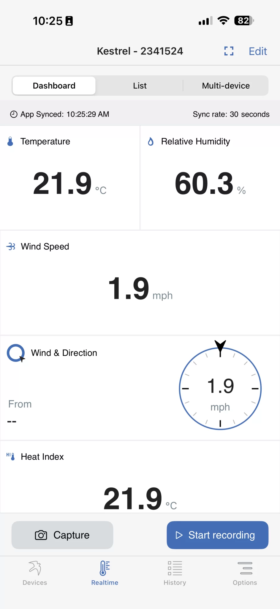
All three were met. The array was confirmed on load and generating throughout. In-plane irradiance was measured with an IEC-compliant irradiance meter at both ends of the capture window and recorded at 752 and 672 W/m². Wind speed sat below 1 m/s throughout, an order of magnitude inside the limit. Ambient temperature and relative humidity were logged continuously by an environmental data logger and the means across the capture window were applied as the radiometric inputs for analysis.
Capture was by uncrewed aircraft carrying a radiometric thermal sensor, flown at 20 m above the module surface to a 2 cm ground sample distance, with survey-grade satellite positioning. Reflected apparent temperature was measured directly from an on-site sky thermogram rather than estimated, and emissivity was determined from the surface condition and the capture geometry. Seven thermograms were then analysed against those parameters.
- Included: thermal assessment of all module-facing surfaces within the array, classification of any anomaly against the standard, and a certified report with the full thermogram set annexed.
- Excluded: electrical testing of any kind, intrusive investigation, inverter diagnostics, on-roof electrical work and remedial works. Findings are areas warranting further investigation by a suitably qualified contractor.
What did the thermal survey find?
No module on the array carried a classified anomaly. That is the headline, and the way it was established is the part worth explaining.
Every thermogram carries its own baseline. A healthy, uniformly irradiated module within the same image is measured and becomes the reference for that image, so a differential is always taken between two values captured at the same instant, under the same sky, at the same radiometric parameters. Any error affecting one affects the other and largely cancels between them. The anomaly reference threshold is that baseline plus 4°C. Across the seven thermograms the baseline held within a range of 2.4°C, which is what a uniformly performing module population looks like.
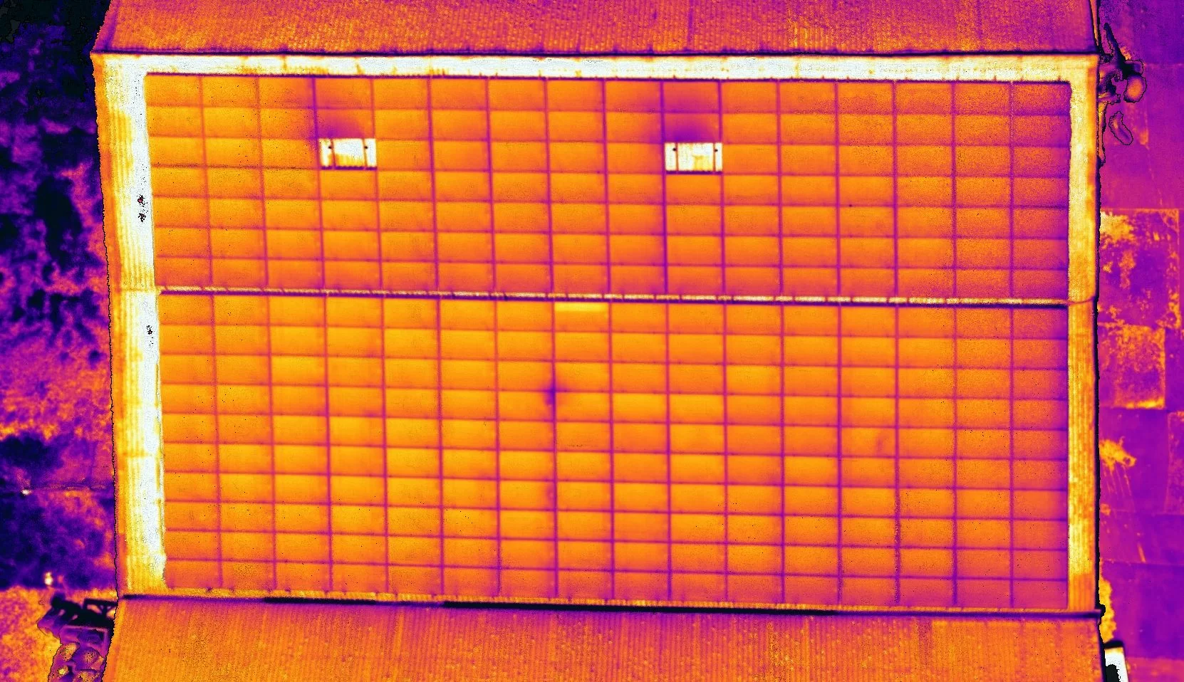
Two discrete warm points were measured, in adjacent modules, at differentials of 3.9°C and 3.4°C above the baseline for the thermogram concerned. Both sit below the classification threshold, so neither is a classified anomaly. Both present as compact, square features bounded within a single cell, with no spread into neighbouring cells and no elevation of the module as a whole. That morphology is consistent with early cell-level heating. Proximity to the module boundary raised the junction box as an alternative reading, but a junction box presents as a broader and less regular form following the box body rather than a defined cell square, so the cell interpretation was preferred on the evidence available. Both were recorded as Advisory monitoring observations carrying a Degradation Trajectory consequence.
What does the outcome mean for the asset owner?
The array is in normal thermal condition for a system in service. At the differentials measured, neither observation carries a measurable effect on output and neither approaches any absolute temperature at which a safety consideration would arise. They are not faults. They are two positions on the array that are now on record, with a number attached, so that a future inspection can test whether anything has changed.
That is the practical value of recording sub-threshold behaviour rather than discarding it. Cell-level heating mechanisms can be progressive, and the useful question at the next inspection is not whether the points are present but whether the differential has grown. Compared against that survey’s own baseline rather than against the absolute temperatures recorded here, that is a straightforward check.
One qualification is stated plainly in the report. The inverter was mounted out of reach and no module-level device information was obtainable, so it could not be established whether module-level electronics are fitted to this array. Where such devices are present they suppress mismatch between modules by design, and string-scale thermal behaviour does not present to a survey of this kind. The absence of string-scale signatures here is therefore not evidence of string-circuit health, and the report says so rather than allowing a broader claim to be read into a clear result.
- Retain the report as the baseline reference for the array, including the recorded conditions and radiometric parameters, so a later survey can be tested for comparability before any difference is read as change.
- Revisit the two recorded cell positions at the next scheduled inspection and compare against that survey’s own baseline.
- Where the electrical architecture becomes known, for example from commissioning documentation or an inverter nameplate, record it, because it changes what a thermal survey can be expected to reveal.
The report was issued as a certified detailed inspection under Clause 5.1(b) of IEC 62446-3:2017, signed under the personal certification of our Level 3 Master Thermographer and carrying an AATL-trusted digital signature.
Why certify a clear result at all?
A report that says no faults were found asserts an absence, and an absence cannot be checked. A report that names the threshold applied, records the conditions under which the array was assessed, states the module population captured and lists the fault categories actively looked for is making a claim a reader can test. That is the difference between a clear result and a reassuring one, and it is why the declaration on a clear job carries the same rigour as the findings section on an adverse one.
Planning a solar inspection programme across your estate?
Drone Media Imaging, a trading name of VisualChaos Studios Ltd, delivers solar PV thermographic inspection under IEC 62446-3:2017, with analysis and certification by a Level 3 Master Thermographer. Core coverage is Sussex, Hampshire, Kent and Surrey, travelling throughout the UK, Ireland and Europe.