
On a Clad Building, the Repeat Is the Baseline
Thermal bridging is the name for a route that lets heat bypass the insulation. On a house it tends to be a lintel, a floor edge or a wall tie. On a commercial or industrial building the routes are different, and there are usually a great many more of them. A clad, steel framed building is assembled from panels, sheets and fixings, and every one of those components meets something else at an edge, a joint or a screw.
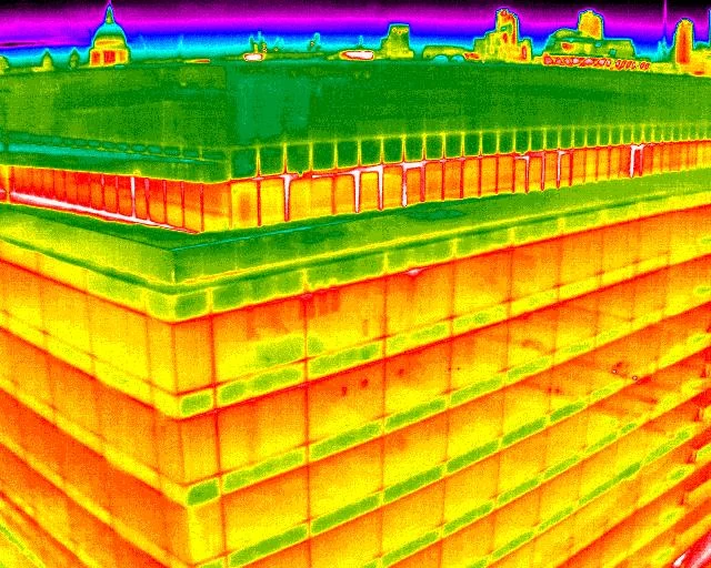
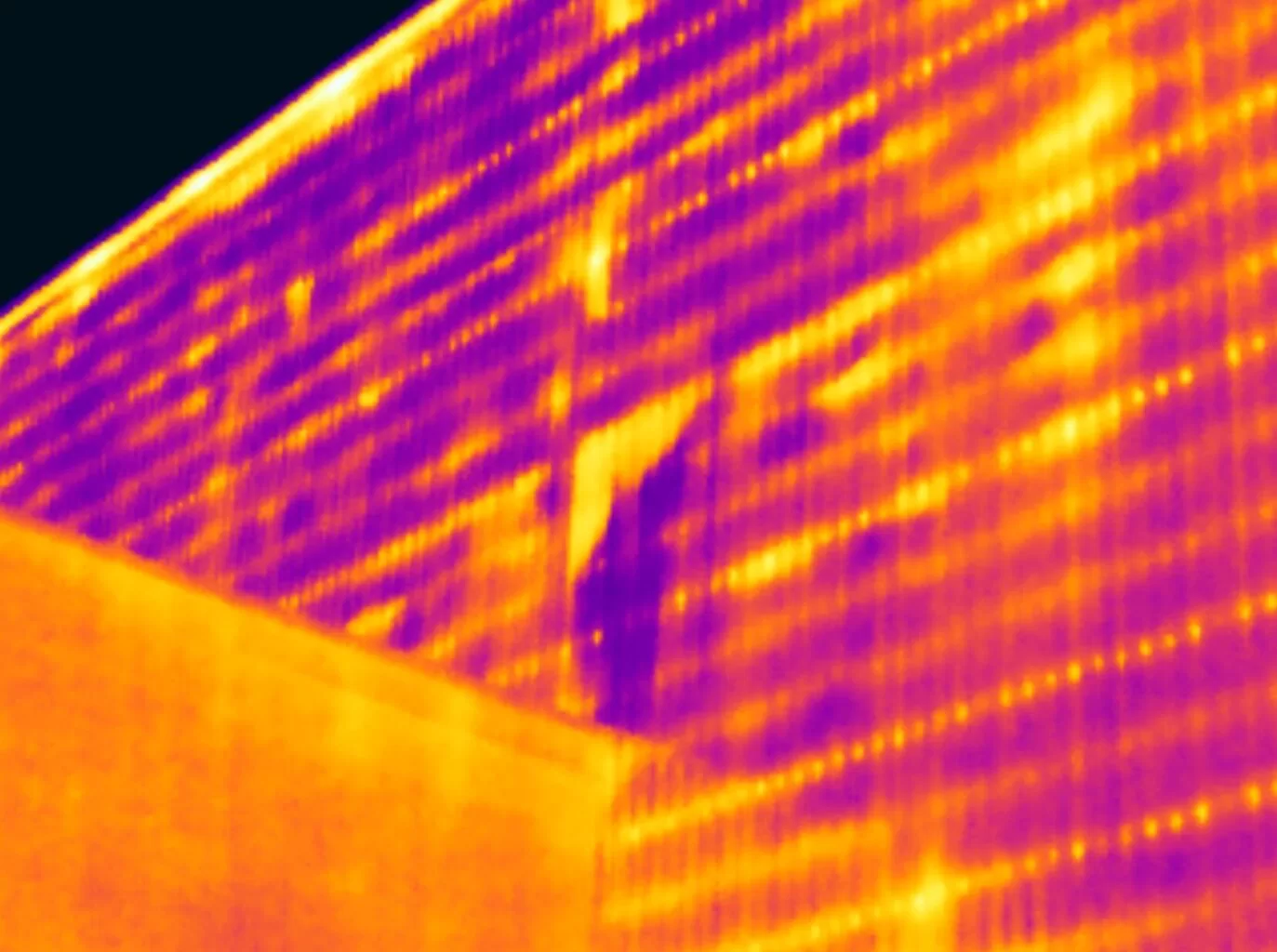
That changes what a thermal image of the building looks like. Instead of a few isolated features, the surface often carries a regular pattern of lines and points that follow the structure behind it: rows of fixings along the rails and purlins, joints between panels, the edges of rooflights and the line where the cladding meets the base of the wall. Much of that pattern is simply the building behaving as it was built.
So the useful question is rather different from the one most people ask. It is not whether bridging is present, because on a building of this kind some almost always is. It is where the pattern departs from itself, and what that departure is most likely to mean. Answering it needs the whole roof and every elevation captured in the same way, which is where working from the air earns its place.
Blog Content TL;DR...
The short version, for anyone responsible for a large clad building.
- On steel framed, clad buildings, thermal bridging usually appears as a regular pattern that follows the structure: fixing lines, panel joints, rooflight edges and the base of the wall.
- Much of that repeat is the building as built, so it is recorded as the baseline rather than reported as a string of separate faults.
- The findings that matter are the departures: a joint that reads differently from its neighbours, a run of fixings that breaks rhythm, or steel that passes straight through the envelope.
- Large buildings are rarely heated evenly, so the survey has to know which zones are heated before any pattern can be read at all.
- Bare metal reflects strongly and coated metal far less, so material and viewing angle are handled deliberately rather than assumed.
The repeat tells you how the building was put together, and the break in the repeat tells you where to look.
Why Clad Buildings Bridge in Patterns
Panels, fixings and steel, repeated across the whole envelope
Most commercial and industrial sheds share a family resemblance. A steel frame of columns and rafters carries lighter secondary steel, the rails on the walls and the purlins on the roof, and the envelope is hung from that secondary steel as insulated panels or as sheets with insulation between them. It is a fast, economical way to enclose a very large volume, and it makes the envelope a kit of repeated parts.
Every repeated part has an edge
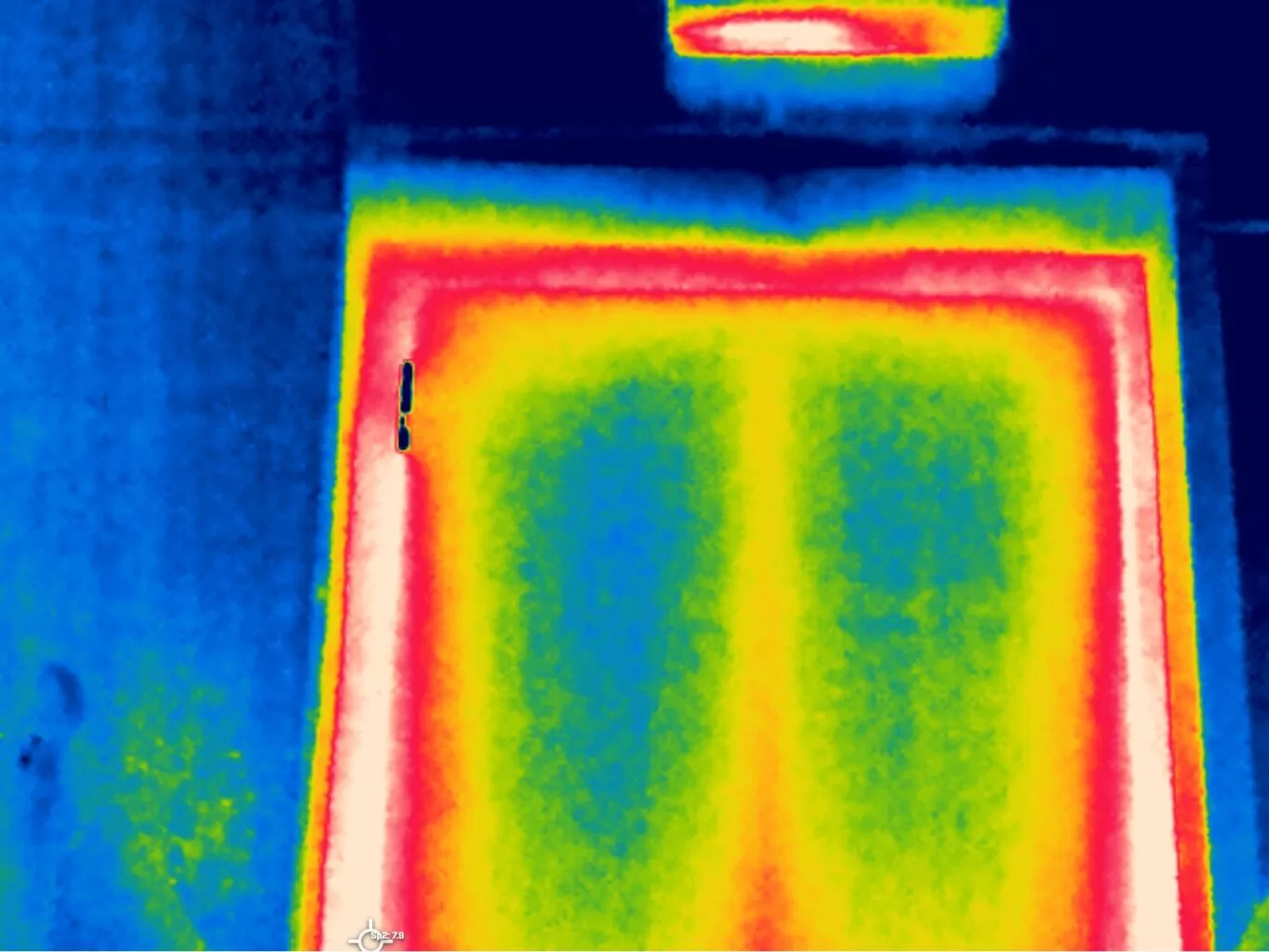
Each panel or sheet is held on with fixings that pass through it into the steel behind, usually in straight rows at regular spacing. Each one meets its neighbour at a joint or a lap. Rooflights, gutters, doors and louvres interrupt the field and have to be sealed around. Where any of these components conducts heat more readily than the insulated panel around it, or where insulation is compressed or missing at an edge, the outside face runs slightly warmer on a cold night. Individually these are small. Repeated across a large roof, they form a grid.
That grid is not a defect list. It is a picture of how the building was assembled, and it is the most useful thing on the image, because it gives every finding something to be measured against. A single warm fixing means little. A fixing that reads warmer than the others along the same rail, captured in the same minute, means a great deal more.
why cladding fixings show on a thermal image, thermal imaging a steel framed warehouse from the air, how to read a repeating pattern on a thermal surveywhy cladding fixings show on a thermal image, thermal imaging a steel framed warehouse from the air, how to read a repeating pattern on a thermal survey
Reading the Break in the Repeat
A thermal camera does not see bridging. It sees surface temperature, and on a clad building at night the outside face settles close to the temperature of the air and the sky above it. Wherever heat reaches that face more easily from inside, it sits a little higher than the surface around it. Because the components repeat, so does the pattern, and that repetition is what makes the analysis possible.
What a departure tends to look like
The findings worth reporting are the places where the pattern stops behaving like itself. A panel joint that reads as a broader or warmer line than the joints either side of it may point to a seal or an insulation gap along that edge. A run of fixings that is warmer along one bay than the rest can follow a local change in the build, or a later repair. A bright line at the eaves, or along the foot of the cladding where it meets a masonry base wall, marks a junction worth a closer look. And steel that passes right through the envelope, a canopy bracket or a support for plant or signage, tends to read as a distinct point or strip that belongs to no pattern at all.
Why the whole building has to be captured the same way
None of this can be read from a handful of frames. A departure only shows as a departure against the run of undisturbed pattern beside it, captured within the same period under the same conditions. That is why roofs and elevations are worked in overlapping passes at a consistent distance and angle, with the conditions logged as the work proceeds. On a large, low building the roof is often the greater part of the envelope, and it is the part least visible from the ground, which is where an aerial survey adds most. The wider method is set out on our building heat loss survey page.
What the Survey Needs, and What It Cannot Say
Commercial buildings bring conditions that a house rarely does, and most of them affect whether a thermal pattern can be read at all. The limits are worth setting out plainly, because they decide what the survey can honestly deliver.
Heat has to be flowing, and flowing evenly
The method depends on a steady temperature difference between inside and outside, held long enough for the fabric to settle, with no sun on the faces being surveyed. Large buildings are seldom heated evenly. A warehouse floor may be barely heated while the offices at one end are kept warm, and loading doors that open through the night can change the inside of a bay in minutes. So before any flight, the survey has to establish which zones are heated, to what set point and for how long, and which doors will stay closed. An unheated zone does not show bridging, however much of it there is, and a zone that has just been opened up will not show it reliably.
Metal answers the camera differently
Bare and shiny metal emits very little and reflects a great deal, so its apparent temperature can be dominated by the sky and its surroundings rather than by the surface itself. Coated, painted and weathered metal behaves far more like ordinary building fabric. Flashings, trims and exposed fixings are therefore identified from the matching daylight imagery and treated individually, rather than read at face value.
It locates, it does not diagnose
A departure in the pattern is a place to investigate, not a proven defect. The survey reads the outer face and infers what lies behind it, and where two explanations remain open the report says so. No U-value, heat loss rate or energy figure comes out of a thermal image. Findings are reported as located and graded irregularities, and as areas warranting further investigation by a suitably qualified contractor.
Emissivity is how efficiently a surface radiates compared with a perfect emitter, and it is the correction that most affects a thermal reading. Most building fabric, including painted and coated surfaces, sits high on that scale and reads reliably. Bare, polished or shiny metal can sit very low, which means much of what the camera receives from it is radiation reflected from the sky, neighbouring buildings or nearby plant rather than energy emitted by the metal itself.
On a clad building this is handled by method rather than by assumption. Emissivity and reflected apparent temperature are established on site against the actual surfaces, and metallic surfaces are recorded and assessed individually by the analyst. Imaging is held within roughly 30 to 45 degrees of the perpendicular, because emissivity falls and reflection rises at glancing angles. Every thermal frame is paired with daylight imagery, so that each reading can be tied to a material. On a large roof, that pairing is what stops a reflection being reported as heat loss.
Governing Standards and Scope
- Thermographic inspection, analysis and reporting are conducted by Steve Fisher, ITC Level III Certified Master Thermographer (Infrared Training Centre; Certification #205722059), practising in accordance with the frameworks of ISO 18436-7:2014, ASNT SNT-TC-1A and ANSI/ASNT CP-105, and BINDT CMGEN Appendix B (UK training governance).
- Inspection methodology is aligned with BS EN ISO 6781-1:2023, the detection of heat, air and moisture irregularities in buildings by infrared methods. Findings are reported as located and graded thermal irregularities, never as calculated thermal performance.
- No U-value, heat loss rate or energy performance figure is derived from thermographic data, and none is implied. Those require calculation from the construction or in-situ heat flux measurement.
- Emissivity and reflected apparent temperature are established on site against the actual surfaces surveyed, with metallic surfaces recorded and assessed individually, and recorded with the data alongside the environmental conditions at the time of capture.
- Findings are reported as areas warranting further investigation by a suitably qualified contractor. No building survey, structural assessment or condition grading is offered or implied, and Drone Media Imaging holds no surveying qualification.
- Drone Media Imaging provides survey, analysis and reporting. No remedial work, retrofit design or specification is offered or implied.
Tell Us About the Building and How It Is Heated
Send us the address, the approximate footprint and height, and a short note on how the building is heated and used, including any zones that are not heated at all. You will get a fixed price back with the deliverables set out in plain words, and an honest view on whether the building suits an aerial survey. We work across Sussex, Hampshire, Kent and Surrey, travelling throughout the UK, Ireland and Europe, and thermography work travels further still.
related posts

A thermal camera does not measure temperature, it infers one from the radiation reaching its lens. That inference depends on emissivity, reflected apparent temperature, distance and the state of the air in between, all of which the thermographer supplies. Get them wrong and the camera still reports a confident figure. This piece sets out what has to be controlled to make a thermogram measurable, why it matters more on some surfaces than others, and what to ask a supplier.
An inspection happens on one morning, but its photographs are usually needed months later by somebody who was not there. What makes them usable then is not the drama of the aerial view. It is whether each observation is marked where it sits, whether close detail is paired with a frame that places it, whether coverage is systematic enough that absence means something, and whether the set can be navigated at all.
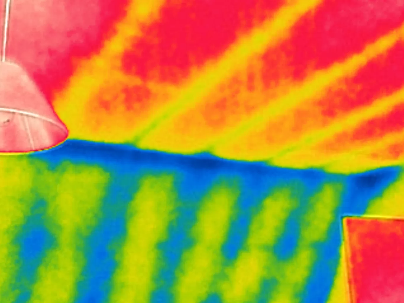
On most pitched roofs a ventilated loft sits between the tiles and the insulation, so an aerial thermal image of the roof is an indirect view of what lies beneath. This piece explains how cold and warm roofs read differently from the air, why the cold night sky is reflected by and draws heat from every roof surface, and which checks turn a warm patch on a roof into a finding worth investigating further inside the loft.